Reverse Engineering of a Flash Programmer :: EZP2010
Preface
In today’s adventure I like to take you with me on my journey of reverse engineering another USB device. The EZP2010 is an USB programmer for flash memory as used by mainboard manufactures to store the BIOS, or embedded devices to store the firmware (or settings). When it comes to data recovery on hard drives, or similar storage devices, these flashers can also become handy.
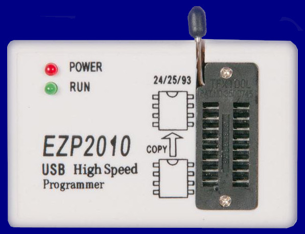
This particular programmer can be bought on many Chinese store or Amazon. The prize range varies form $8 to $24. Unfortunately the software and drivers which come with this programmer are windows only.
The micro controller unit (MCU) used is the C8051F340. It was easily identified by opening the enclosure and looking at the markings of the MCU.
Start of an adventure

Realistic representation of me, being outside and enjoining it. But without the running and the joy. I also have shoes and longer trousers.
As already mentioned, this adventure will be about reversing the USB protocol of this programmer.
To start with analyzing the programmer a virtual machine would be an easy solution. And here I came across another problem this programmer has. It is not necessarily the fault of the hardware, but of the drivers and software provided to use it.
I worked on this project on different host machines and different versions of a virtual machine. The main difference was the architecture used. One VM was a 64bit Windows 10 and the other a 32bit Windows 10. Trying to run the software on a 32bit system failed, the software was unable to connect to the programmer, but I could not find any drawback in using a 64bit Windows.
Information Gathering

Me looking for information.
The most obvious things to do are lsusb and opening up the enclosure. Lsusb will output all connected USB devices connected on a Linux machine and get the description, as well as the vendor id and product id for device identification.
The output of lsusb gives information on how to talk to the device. With the product and vendor id the verbose output of lsusb can be limited to display only the device of interest. USB devices have separate input and output “endpoints”. On this particular device the endpoint to send our data to is 0x02 EP 2 OUT and 0x81 EP 1 IN where I can receive the responses and incoming data.
$ lsusb
\[...\]
Bus 003 Device 027: ID 10c4:f5a0 Cygnal Integrated Products, Inc.
\[...\]
$ lsusb -v -d 10c4:f5a0

Bus 003 Device 027: ID 10c4:f5a0 Cygnal Integrated Products, Inc.
Couldn't open device, some information will be missing
Device Descriptor:
  bLength                18
  bDescriptorType         1
  bcdUSB               2.00
  bDeviceClass            0
  bDeviceSubClass         0
  bDeviceProtocol         0
  bMaxPacketSize0        64
 ** idVendor           0x10c4 Cygnal Integrated Products, Inc.
  idProduct          0xf5a0**
  bcdDevice            0.00
  iManufacturer           0
  iProduct                0
  iSerial                 0
  **bNumConfigurations      1**
  Configuration Descriptor:
    bLength                 9
    bDescriptorType         2
    wTotalLength       0x0020
    **bNumInterfaces          1**
    bConfigurationValue     1
    **iConfiguration          0**
    bmAttributes         0x80
      (Bus Powered)
    MaxPower              480mA
    Interface Descriptor:
      bLength                 9
      bDescriptorType         4
      **bInterfaceNumber        0**
      bAlternateSetting       0
      **bNumEndpoints           2**
      bInterfaceClass         0
      bInterfaceSubClass      0
      bInterfaceProtocol      0
      **iInterface              0**
      Endpoint Descriptor:
        bLength                 7
        bDescriptorType         5
        **bEndpointAddress     0x81  EP 1 IN**
        bmAttributes            2
          Transfer Type            Bulk
          Synch Type               None
          Usage Type               Data
        wMaxPacketSize     0x0040  1x 64 bytes
        bInterval               5
      Endpoint Descriptor:
        bLength                 7
        bDescriptorType         5
        **bEndpointAddress     0x02  EP 2 OUT**
        bmAttributes            2
          Transfer Type            Bulk
          Synch Type               None
          Usage Type               Data
        wMaxPacketSize     0x0040  1x 64 bytes
        bInterval               5
In the beginning of this post, I already mentioned the used MCU for this programmer. It will not be of much of significance for this project but information is always nice to have. So the C8051F340 by Silicon Labs can do different things, but the most important ones are Universal Serial Bus (USB) Controller and the Serial Peripheral Interface (SPI). The USB connection manages the communication between the host (PC) and the device. The SPI will manage the programming of the flash memory.
VM Setup
As previously told, I have used a 64bit Windows 10 virtual machine. For capturing the USB traffic I used Wireshark and USBPcap. The workflow is the same as it is with network packet capturing. Instead of selecting a network interface, a USB root hub is selected where the device of interest is connected.
Packet Capturing
At first I setup the packet capturing with Wireshark and select the USB root hub I want to monitor - and where I connect the programmer.
The next steps include a straight forward workflow, after Wireshark was configured and running. I started the programmer software. If Wireshark is configured correctly it reports the first packets captured during device initialization and opening the device by the software.
As there are not special device specific commands transferred during device and software initialization, these steps won’t be necessary to cover here.
Now, if I press any button in the software to interact with the programmer, a corresponding reaction should be captured in Wireshark. To keep track which action resulted in which packets, Wireshark supports comments for their pcapng fileformat. When I press a button in the software, I comment the first packet captured and the last packet incoming.
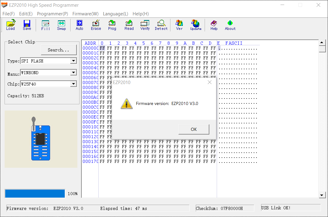
To keep it simple, I will illustrate this on the command to request the firmware version of the device. The button is labeled “Ver” in the toolbar. When clicked, two messages are transmitted between the host and the device which are captured by Wireshark.
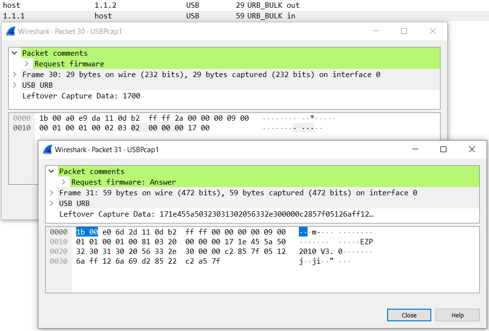
In the screen shot above, I commented the outgoing packet from the host to the programmer and labeled it “Request firmware”. The answer - which came immediately after the outgoing message. I labeled the packet as “Request firmware: Answer”. When I look into this dump a few days later, I will still be able to figure out what the cause of these packets were.
The firmware version request command are two bytes (Leftover Capture Data in the Wireshark window) 0x17 0x00. The answer will be the version string EZP2010 V3.0 and a few more bytes.
This way I worked through every function provided by the software to capture all possible commands. The “Read” and “Prog” ROM commands will produce a few more packets depending on the size of the flash chip. The outgoing or incoming packets either be the contents read from the flash chip or the data going to be written to the flash chip.
While capturing the packets should be almost enough, a look at the decompiled code of the program can help finding possible pitfalls.
Reversing the Programmer Windows Software
This part was not really necessary, but helped in the process of packet analysis as well in matching the captured command packets with a function in the disassembled program.
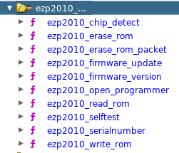
Each command supported by the programmer has a corresponding function. Matching all functions and command codes, I could see if I had found and captured all available commands the programmer hardware supports.
Refactoring the code generated by Ghidra, the result of reversing engineering a function could look like this. I am going through the code to request the firmware version.
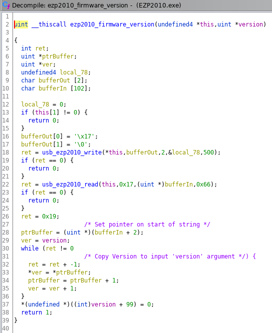
The code in the screenshot above sends two bytes to the programmer and than tries to read 23 (0x17) bytes as answer. The while loop at the bottom copies the contents of the bufferIn variable into the output argument variable version.
Just to clarify, the variables are pointers to a memory location at this point. the variable will store the address where the value (version string) is stored.
Writing a POC

Python POC
I often try to build my first proof of concept, or to validate my ideas, with a small Python program.
The code is based on the tutorial example provided by PyUSB. I just added the other endpoint to read the responses from the programmer.
#!/usr/bin/env python
import usb.core
import usb.util


dev = usb.core.find(idVendor=0x10c4, idProduct=0xf5a0)
dev.set_configuration()

cfg = dev.get\_active\_configuration()
intf = cfg\[(0, 0)\]

epo = usb.util.find\_descriptor(intf, custom\_match=lambda e:
                               usb.util.endpoint_direction(e.bEndpointAddress)
                               == usb.util.ENDPOINT_OUT)
epi = usb.util.find\_descriptor(intf, custom\_match=lambda e:
                               usb.util.endpoint_direction(e.bEndpointAddress)
                               == usb.util.ENDPOINT_IN)

epo.write(\[0x17, 0x00\])
s_buf = ''.join(\[chr(c) for c in epi.read(256)\])
print(s_buf)
Executing the test program will give something like “EZP2010 V3.0” and a few more additional bytes. Which should be expected, as the receiving buffer is defined with a size of 0x17 (23 bytes).
At the moment I have not looked into the remaining bytes and their purpose. The original software does not display any more information, but the version string.
C POC
Doing it in C requires a bit more work. Below is the whole POC program source I have used to verify my work. The main part of the program is the USB device tree traversal to open and configure our target device. There is an easier to use function to do this with libusb.
But the function libusb_open_device_with_vid_pid() gave me a bit of a trouble, as I was not able to configure the device properly to write and read data.
    #include <stdlib.h>
    #include <stdio.h>
    #include <unistd.h>

    #include <libusb-1.0/libusb.h>

    #define EZP2010_VID 0x10c4
    #define EZP2010_PID 0xf5a0

    static libusb_device_handle *devh = NULL;

    libusb_device_handle *open_ezp2010()
    {
        ssize_t devc;
        libusb_device **dev_list;
        static libusb_device *dev = NULL;
        struct libusb_device_descriptor dev_desc;
        struct libusb_config_descriptor *dev_cfg = NULL;
        const struct libusb_interface *intf = NULL;
        const struct libusb_interface_descriptor *intf_desc = NULL;

        int r = 0;

        devc = libusb_get_device_list(NULL, &dev_list);
        if (devc < 1)
            return NULL;

        for (int i = 0; i < devc; i++) {
            dev = dev_list[i];
            if (libusb_get_device_descriptor(dev, &dev_desc))
                continue;

            if ((dev_desc.idVendor != EZP2010_VID || dev_desc.idProduct != EZP2010_PID))
                continue;

            r = libusb_open(dev, &devh);
            if (r < 0) {
                perror("libusb_open");
                return NULL;
            }

            for (int j = 0; j < dev_desc.bNumConfigurations; j++) {
                if (libusb_get_config_descriptor(dev, j, &dev_cfg))
                    continue;

                for (int k = 0; k < dev_cfg->bNumInterfaces; k++) {
                    intf = &dev_cfg->interface[k];
                    for (int l = 0; l < intf->num_altsetting; l++) {
                        intf_desc = &intf->altsetting[l];
                        if (libusb_kernel_driver_active(devh, intf_desc->bInterfaceNumber))
                            libusb_detach_kernel_driver(devh, intf_desc->bInterfaceNumber);

                        libusb_set_configuration(devh, dev_cfg->bConfigurationValue);
                        libusb_claim_interface(devh, intf_desc->bInterfaceNumber);

                        int e = 0;
                        while (libusb_claim_interface(devh, intf_desc->bInterfaceNumber) \
                                && (e < 10)) {
                            sleep(1);
                            e++;
                        }
                    }
                }

                libusb_free_config_descriptor(dev_cfg);
            }
            return devh;
        }

        devh = NULL;
        return NULL;
    }

    int main(int argc, char *argv[])
    {
        int r = 0;
        int transferred = 0;
        unsigned char buf[256];

        r = libusb_init(NULL);
        if (r < 0)
            return 1;

        open_ezp2010();

        buf[0] = '\x17';
        buf[1] = '\x0';
        r = libusb_bulk_transfer(devh, 0x2, buf, 2, &transferred, 500);
        if (r < 0) {
            perror("libusb_claim_interface");
            fprintf(stderr, "Error: %s\n", libusb_strerror(r));
        }
        printf("Bytes sent: %d\n", transferred);

        r = libusb_bulk_transfer(devh, 0x81, buf, 0x20, &transferred, 500);
        if (r < 0) {
            perror("libusb_claim_interface");
            fprintf(stderr, "Error: %s\n", libusb_strerror(r));
        }
        printf("Bytes received: %d\n", transferred);
        printf("Packet: %s\n", buf);

        libusb_release_interface(devh, 0);
        libusb_reset_device(devh);
        libusb_close(devh);

        libusb_exit(NULL);

        return 0;
    }
Future Work
My idea is to integrate it into existing programmer software, or to implement a small standalone tool for this programmer.
There is also still some research to do on the support for different flash chips. The original software provides a database with known and supported flash chips.
Looking at the code and figuring out the database structure might be the next step in further reverse engineering and developing further support for this programmer.