Reverse Engineering of the SkyRC MC3000 Battery Charger USB Protocol
Software Requirements
Decompiler for .NET programs
The implementation of the protocol is then written in Python. Let’s hear what the curator has to say:
Tell me about Python.
> Wow. Much Snake. Easy programming!
>
> \- Doge
Tell me about dotPeek.
> Easy decompilation. Readable syntax. Very easy.
>
> \- Doge
Analyzing MC3000_Monitor
Decompiling
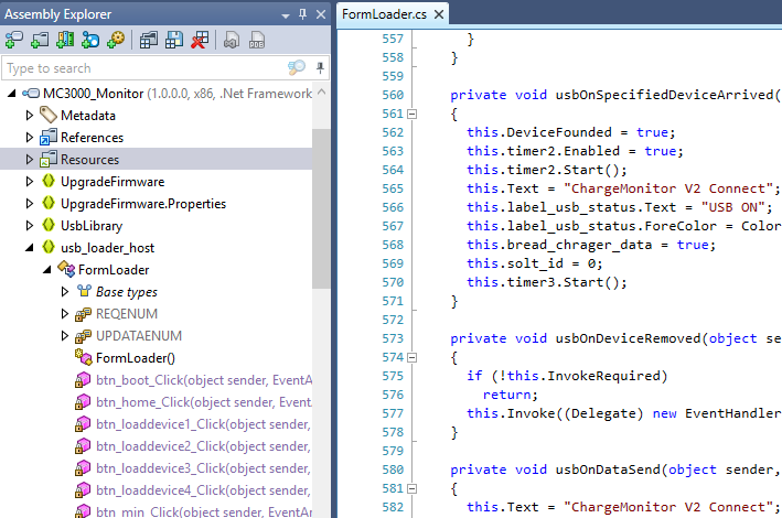
Start dotPeek and use Drag’n’Drop to load the Application. Or uSe CtRL+O anD LoCATe tHe fILe uSiNg ThE bOrwsEr. I am not your mother! The file will show up in the Assembly Explorer. You can expand and collapse nodes within the tree. Familiarize yourself with the program structure. Try to find the entry point or other “important” functions, modules or resources.
If you right click the MC3000_Monitor node you can export the project with individual source files. This project is stored as *.cs source files.
You should now have either the project loaded into dotPeek or - in addition - saved it as project and/or loaded it into Visual Studio (VS) (Not covered here). I cannot afford VS. Still saving money to upgrade my IDA Pro license.
 Intermission:
 This is the curator speaking, and I command you to stop whining!.
As you can see, a lot of professionalism.
Exploring the code
For me the easiest way to begin, is to find parts of code where user interaction is required. Run the program and look at the user interface. In this particular case we have four buttons next to a label each.
Lets explore the code in dotPeek and see if we can find some code that might look familiar.
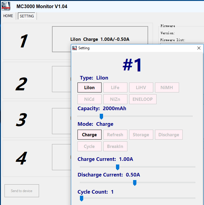
Pressing one of the buttons opens another window where you can configure the charger slot. By further reading through the different functions you might come across the function InitializeComponents():void. Each window element gets setup and function callbacks/events are registered.
You eventually find something like this (see the picture below).
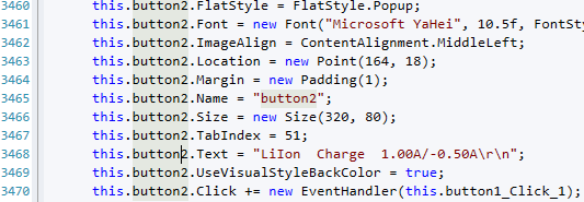
Let’s put on our smart looking spec ticals and read line 3468 and 3470. Line 3468 is the creation of the button text, which should look familiar. If not, search for hints on this page. Line 3470 binds a function to the button press. With a Ctrl+Left click we jump to the function definition in dotPeek.
The function private void button1_Click_1(object sender, EventArgs e) is pretty simple to read. When the button is clicked, get the button name (e.g. “button1”1) and check if there is either the number 1, 2, 3 or 4 in the name.
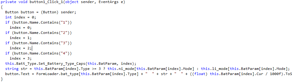
Can you see the problem here? There is no error handling if button number is smaller than one or greater four. As an array is indexed, the program will probably crash. At this point we don’t care. We want to make our own library, to make it better or different. After the name checking to know which slot is addressed, it calls a function public void Set_Battery_Type_Caps(ChargerData[]data, int index). The functions sets the parameters of each battery slot and saves the values to an array.
This function sums up all parameters we need to know to setup a charger slot by or self. And we now know the default values. The below listing is the exception code, if anything goes wrong in the code above, but not when using an index outside bounds.
// Battery.cs:1195

data[index].Type = 0;
data[index].Caps = 2000;
data[index].Mode = 0;
data[index].Cur = 1000;
data[index].dCur = 500;
data[index].End_Volt = 4200;
data[index].Cut_Volt = 3300;
data[index].End_Cur = 100;
data[index].End_dCur = 400;
data[index].Cycle_Mode = 0;
data[index].Cycle_Count = 1;
data[index].Cycle_Delay = 10;
data[index].Peak_Sense = 3;
data[index].Trickle = 50;
data[index].Hold_Volt = 4180;
data[index].CutTemp = 450;
data[index].CutTime = 180;
The data structure ChargerData can be looked up as well, but the above listing is a little bit easier to read.
What we haven’t seen at this point were bytes transferred to or from the device.

At this point, there are multiple ways to get a good starting point on finding the functions where data is transmitted or received. One option is to look at the Assembly Explorer again for functions names of possible interest.
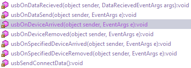
These convenient looking functions. Or should I say obvious function names are obvious, are used to handle the USB device communication. Try right clicking a function to find out where it is used. I have used usbOnDataRecieved. In the below window with search results you can find a reference located in the constructor2 of the class FormLoader.
// FormLoader.cs:352

this.usb = new UsbHidPort();
this.usb.ProductId = 1;
this.usb.VendorId = 0;
this.usb.OnSpecifiedDeviceArrived += new EventHandler(this.usbOnSpecifiedDeviceArrived);
this.usb.OnSpecifiedDeviceRemoved += new EventHandler(this.usbOnSpecifiedDeviceRemoved);
this.usb.OnDeviceArrived += new EventHandler(this.usbOnDeviceArrived);
this.usb.OnDeviceRemoved += new EventHandler(this.usbOnDeviceRemoved);
this.usb.OnDataRecieved += new DataRecievedEventHandler(this.usbOnDataRecieved);
this.usb.OnDataSend += new EventHandler(this.usbOnDataSend);
These lines above register event handlers with an instance of UsbHidPort. An event might be connecting or disconnecting the device (line: 355-358) or transferred data (line: 359-360). There is nothing special about the connect functions, except for usbOnSpecifiedDevice... ones. There is a call to stop and stop the timer2 instance. We will look at this object in a second, but first we have a look at usbOnDataSend and usbOnDataRecieved.
// FormLoader.cs:513

private void usbOnDataRecieved(object sender, DataRecievedEventArgs args)
{
  if (this.InvokeRequired)
  {
    try
    {
      this.Invoke((Delegate) new DataRecievedEventHandler(this.usbOnDataRecieved), sender, (object) args);
    }
    catch (Exception ex)
    {
      Console.WriteLine(ex.ToString());
    }
  }
  else
  {
    ++this.packet_counter;
    for (int index = 0; index < 65; ++index)
      this.inPacket[index] = args.data[index];
    this.dataReceived = true;
  }
}

...

// FormLoader.cs:580

private void usbOnDataSend(object sender, EventArgs e)
{
  this.Text = "ChargeMonitor V2 Connect";
  this.label_usb_status.Text = "USB ON";
  this.label_usb_status.ForeColor = Color.Green;
}
The usbOnDataSend function is boring, and we can ignore it. There is no active sending of data to the usb device. UsbOnDataReceived on the other hand is actually doing something with an buffer of 64 bytes (line: 528-531).
When data is received an internal packet_counter is increased. Each packet has a size of 64 bytes (line: 529). The packet is copied into the inPacket array, and the dataReceived variable is set to true.
My guess is, that somewhere, something, somehow, might be, is waiting for a packet to arrive and waits until dataReceived is true. In dotPeek we can use the magic function “Find Usages” again, to find out more.

Prototyping and understanding the program
Remember the timer2 instance mentioned before? No, try to find the hint on this page.
// Formload.cs:1219

private void timer2_Tick(object sender, EventArgs e)
{
  byte num1 = 0;
  if (!this.dataReceived)
    return;
  this.dataReceived = false;
  if ((int) this.inPacket[1] == 240)
{
  if (this.bwrite_chrager_data)
    return;
  int num2 = (int) MessageBox.Show("OK!");
}
else if ((int) this.inPacket[1] == 95)
  this.Get_Charge_Data((int) this.inPacket[2]);
else if ((int) this.inPacket[1] == 90)
{
  this.Get_System_Data((int) this.inPacket[3]);
}
else
{
  if ((int) this.inPacket[1] != 85)
    return;
  for (int index = 1; index < 64; ++index)
    num1 += this.inPacket[index];
  if ((int) num1 != (int) this.inPacket[64])
    return;
The timer2 will process incoming data send from the device to the connected computer. The code begins with comparing index 1 of the inPacket with a series of values.
By looking at the code we might be able to assume we are looking at the first bytes necessary to communicate with the device. Here are some guesses:
Value           Description

240 (0xf0)      Confirmation sent by charger.
95 (0x5f)       Get charger data by information provided in index 2,
                which is an number[^fn:4].
90 (0x5a)       Get system data by information provided in index 3,
                which is a number.
85 (0x55)       Do not process the packet here. Otherwise calculate
                the sum of all bytes in `num1` and compare it to the
                information stored in index 64.
If these checks do not result in an premature return, the values from inPacket are copied into variables. Some variable names are recognizable and help in our guessing game to find out what this function does.
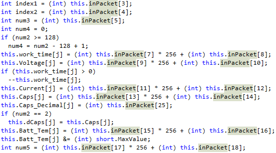
With the looks of it we are reading battery information. As an example on how the packet is decoded, we will have a look at the following code:
this.Current[j] = (int) this.inPacket[11] * 256 + (int) this.inPacket[12];
The contents of inPacket index 11 and 12 is assigned the the variable Current at index j. Which is irrelevant at this point. But we need to understand what is happing with this multiplication and addition.
The multiplication by 256 is just a different way to express a left shift by 8. What happens, when we take the value 1 and multiply it by 256 or do a left shift by 8? In binary representation it will become very easy to understand.
     1   =>         0b1
   256   => 0b100000000
So what if we take 256 times 1?
256 => 0b100000000
And if we take the value 0b1 and move the 1 exactly 8 positions to the left, like a left shift, duh?
   1 << 0 = 0b1
   1 << 1 = 0b10
   1 << 2 = 0b100
   1 << 3 = 0b1000
   1 << 4 = 0b10000
   1 << 5 = 0b100000
   1 << 6 = 0b1000000
   1 << 7 = 0b10000000
   1 << 8 = 0b100000000
This is just a step by step illustration. Computer do fast. Computer do in single step.
After the left shift, the second value is added to the variable. In other words, we are reading two bytes and concatenate it to have a word (2 bytes).
The same applies to the other functions Get_Charge_Data and Get_System_Data where the inPacket is read.
But how am I supposed to create my own library with this?

This is the part, where you take your favorite language, or a language good for prototyping and begin coding. First challenge would be to connect to the USB device. I am using the pyusb module with Python.
To connect an USB device we want to make sure we are using the right one. To do so, the USB devices can be identified by different properties, and one of them is the vendor and product id. The source of the program might give us enough information we need, as it needs to connect to the charger as well.
The product and vendor id can be found in the function private void usbSendConnectData() and is defined as:
Field       Value
Vendor ID       0
Product ID      1
Reading Data
The people writing the firmware for the charger, did not care to give it some nice values, on the other hand 0 and 1 are nice. With these identifiers, it is possible to connect to our charger.
    import usb
    usb.core.find(idVendor=0, idProduct=1)
This will return a list of devices, even when the list is empty or contains just one element. Set up the USB device further and start building your first packet to send. Before blindly sending commands to the charger, what would be the most destructive - errr - non destructive command: getting device information.
Do some reads on the device without sending anything to it. Eventually you will receive a packet.
In this scenario the packets have a common format for receiving and sending. You might notice a 0x0f at the beginning of each packet. As dotPeek is unable to tell you where it comes from and where it is designed, I am going to spoil it for you.
In file FormLoader.cs in line 201 we find the following definition:
public const byte UART_DATA_START = 15;
The UART3 we are basically telling the charger we are coming over USB. There is also a mobile application to send commands via Bluetooth, but I haven’t done this one, yet.
There is function called Get_System_Data. When we look at the definition of the function the code is very messy.
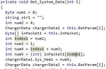
Alot4 of constant values are assigned to variables, which are assigned to variables and then used as index. This looks confusing but the best way is to just begin prototyping it the same way.
num1 = 0
str1 = ''
num2 = 4
# Do not kown this yet
inPacket = raw_packet  # raw_packet is the contents read by pyusb.
index1 = num2
num3 = 1
num4 = index1 + num3
num5 = int(inPacket[index1], 16)  # Python 3: probably bytes as input.
...
And so on. After building your prototyped function you will see parts which can be optimized, but do not care about it too much in the beginning. Try to understand how packets are constructed and what they contain. But for example the num2 = 4 could be removed and replaced with index1 = 4, as num2 is not used after that point.
By breaking the packet down, byte by byte (there are only 64 bytes), we then try to create data structures from it, like the one mentioned in the beginning. Each information gathered so far helps in decoding packets received and to later send packets.
For decoding packets I personally use the [Python struct](https://docs.python.org/3/library/struct.html) module. By reading the definition of Get_System_Data we define a system class, and machine_info as FormLoader.cs calls it.
With struct we define a data structure which can parse the 64 bytes each packet has and apply it to a named tuple in Python. After reading the original decompiled code, I came up with this definition:
#: Machine response data
MACHINE_INFO_STRUCT = '>3xBBBBBBBBBBBBB6sBBhBBBBbB'
#: Tuple for device information
MachineInfo = namedtuple('machine_info',
                         ['Sys_Mem1', 'Sys_Mem2', 'Sys_Mem3', 'Sys_Mem4',
                          'Sys_Advance', 'Sys_tUnit', 'Sys_Buzzer_Tone',
                          'Sys_Life_Hide', 'Sys_LiHv_Hide',
                          'Sys_Eneloop_Hide', 'Sys_NiZn_Hide', 'Sys_Lcd_time',
                          'Sys_Min_Input', 'core_type', 'upgrade_type',
                          'is_encrypted', 'customer_id', 'language_id',
                          'software_version_hi', 'software_version_lo',
                          'hardware_version', 'reserved', 'checksum',
                          'software_version', 'machine_id'])
The struct definition MACHINE_INFO_STRUCT describes how each byte of the packet should be interpreted. In words:
- We decode it as big-endian.
- Ignore 3 bytes as these are protocol commands.
- Read 14 unsigned bytes (0..255), each into a separate variable.
- Read 6 characters or a string of length 6.
- Read 2 individual bytes.
- Read a short (2 bytes).
- Read 4 individual unsigned bytes.
- Read a signed byte (-128..127).
- Read a unsigned byte.
The MachineInfo is a [namedtuple](https://docs.python.org/3/library/collections.html#collections.namedtuple), to make it very easy to assign and access values. When we receive a packet and we have determined the type, we can do something like this:
data = unpack(MACHINE_INFO_STRUCT, response[:32])
machine = MachineInfo(\*data, 0, machine_id)
Sending Data
While reading data is one side, we also need send commands. When optimizing the code the private bool Send_USB_CMD(int Solt, byte CMD) function can be annoying, but refactoring the prototype code will very quickly tell you where to place your bytes.
Whilst the original code is hiding the CMD parameter position behind some index calculations (which lies in nature of decompilation) we can translate the following code:
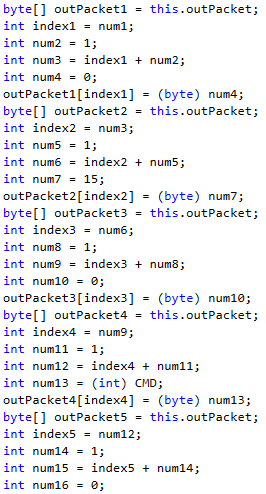
To a single byte-string if we use the Get_System_Data CMD code 95:
\x0f\x00\x5a\x00
One really annoying thing is the index counting. The program starts filling the outPacket at offset 1. Which is actually 0, which is always set to 0x0f. It is protocol definition.
Tricky thing is the real offset 1. It has to be set to a specific value. To find out which one, we have to further investigate the code. This changes depending on the operation you want to call.

Going further through the code, we might find a location where it sets the offset 1 to a other value than 0. Eventually the offset becomes 4. The command so far is now:
\x0f\x03\x5a\x00
Sending this to the device returns no result, therefore we are still missing something. Somewhere was a loop adding up all bytes of packet. This could be a checksum and/or the command is still incomplete. Let’s look at the Send_USB_CMD again. When working through the code, it is help full to take notes.
I have removed a switch-case statement for your convenience.
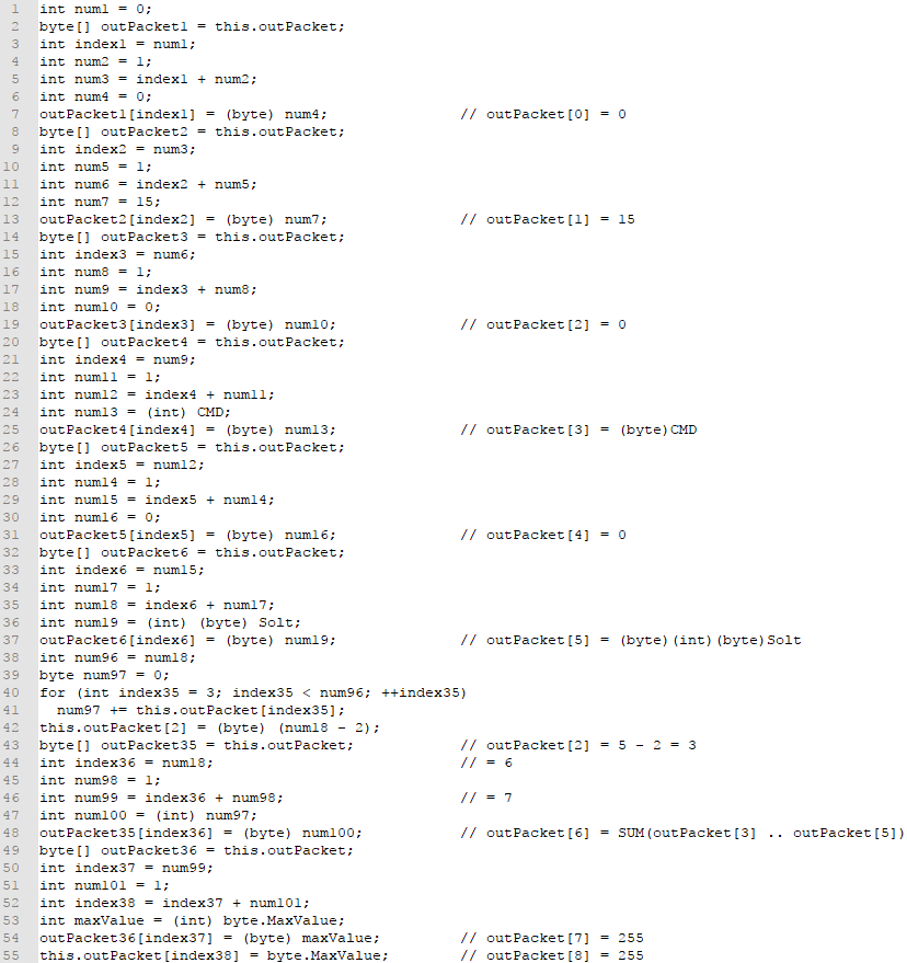
After working through the code, taking notes. the resulting packet for CMD=95, Solt=05 should look like this:
\x00\x0f\x03\x5a\x00\x00\x5d\xff\xff
The two bytes of \xff (255) at the end define the end a packet. Every packet is produced after this schema.
Byte    Description
1       It is always 0, you will learn soon enough why! _ARRGHGGHG_
2       Start of message (Always 0x0f (15)).
3       Calculate the value based on the index.
4       The command op code.
5       It is 0.
6       The slot index (0 to 3 (4 Slots)).
7       The sum of the variable data (Byte 3 to 6)
8       Is always 0xff (255)
9       Is always 0xff (255)
Sending this to the device is still not correct, why? To find out why, delving deeper into the nested classes we find an abomination. The decompiled code for SpecifiedOutputReport.cs in class UsbLibrary.SpecifiedOutputReport, there is this one function:
public bool SendData(byte[] data)
{
  byte[] buffer = this.Buffer;
  for (int index = 1; index < buffer.Length; ++index)
    buffer[index] = data[index];
  return true;
}
The line 19 defines a loop starting at index 1…
With all this knowledge collected the final valid packet to send to your device is:
\x0f\x03\x5a\x00\x00\x5d\xff\xff
That’s it. We have done it.
KTHXBYE!